27 January 2023
15 March 2021
The MWI and ICI imagers will be hosted on the same EPS-SG platforms, providing radiances at microwave (MW) and sub-mm-wave frequencies. One of the novel characteristics of the Level 1 products from these instruments is that time integration is performed over a period shorter than the time necessary to sweep a single projected field of view (FOV) on ground. This implies that there will be several sub-samples available to be provided to the users, and footprints on ground will have different incidence and azimuth angles with respect to each other. Also, for MWI, the FOV of lower frequency channels differs substantially from those at a higher frequency, and from those of ICI. The study, therefore, focused on the use of the Backus-Gilbert (BG) methodology, using the antenna patterns as a priori information to perform the optimal convolution of the radiances observed with channels at various frequencies, to a previously defined target resolution.
Objectives
The objective of the study was to develop a footprint resampling technique, for performing remapping of the L1B MWI and ICI observation into a target FOV, for the following main applications:
- Level 2 processing: for each instrument, the level 1B brightness temperatures from the various channels need to be deconvolved/convolved on a prescribed target FOV, in order to prepare the data for the level 2 product processing.
- Cal/val: during cal/val activities it will be necessary to assess inter-channel and inter-pixel biases among the various channels of MWI and ICI over radiometrically homogeneous targets. As both MWI and ICI will have a suite of channels around 183 GHz, it will be necessary to compare the respective radiances for inter-calibration purposes.
Overview
ICI and MWI are conically scanning instruments having a novel scanning pattern, providing many samples to the users (in the range of 1400 for MWI, 800 for ICI).
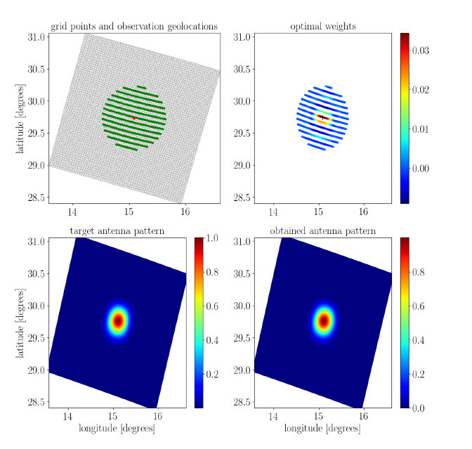
The Backus-Gilbert methodology has been used to obtain a set of optimal weighting coefficients for neighbouring samples, both within the scan and from adjacent scans, to create a remapped representation of the data matching a specified target footprint (Figure 1). A remapped value is a linear weighted combination of data of the channel of concern. The weights were found after a trade-off analysis, by minimisation of a penalty function that considers both the effective noise of the remapped data and the fit to the target footprint. Optimal weights are channel specific, depend on scan position and vary slightly with orbital variations.
Samples from all ICI channels are convolved onto the field of view of ICI-1V, while samples from MWI onto the field of view of MWI-3V.
A simulated MWI and ICI Level1B dataset, covering four reference orbits, has also been generated. The simulation takes into account MWI and ICI instrument characteristics, attitude steering of the platform, surface emissivities and topography, absorption properties of atmospheric species, and cloud and precipitation. A toolbox for such remapping has also been developed. The toolbox and the simulated MWI and ICI Level1B dataset were further used for studying details of the footprint matching application on MWI and ICI, including various types of bias assessments. The study covered technical aspects of the remapping, e.g. identification of how many scan lines need to be taken into account in various type of remapping, how to treat the remapping around swath edges, and what type of simplifications can be performed without introducing any significant errors.
The study indicated that the performance of the remapping of samples from MWI-1 and MWI-2 channels onto the MWI-3V FOVs is limited, due to the large footprint size with respect to the target FOV.
A bias-free convolution has been demonstrated as long as the remapping does not involve a change in incidence angle (i.e. when the incidence angle of the samples to be remapped agree to that of the target channel). However, several MWI and ICI channels have an incidence angle that does not exactly match that of the target and, hence, non-negligible biases, even for cloud-free conditions, were found for some channels. For ICI, the bias is greatest for the dual polarised channels around 243 and 664 GHz, whereas it is small, almost negligible, for the remaining ICI channels. Some of the MWI channels have significant sensitivity to the surface, and the cloud-free bias, therefore, varies with surface type. The greatest cloud-free bias was found for MWI-8V over an ocean surface, whereas the bias over land was found to be significantly lower. However, biases derived for channels with a strong surface sensitivity must be treated with care, in particular for land surfaces. Clouds within the FOV can have a non-negligible influence, on top of the cloud free bias, and the impact varies between channels and phase of cloud.
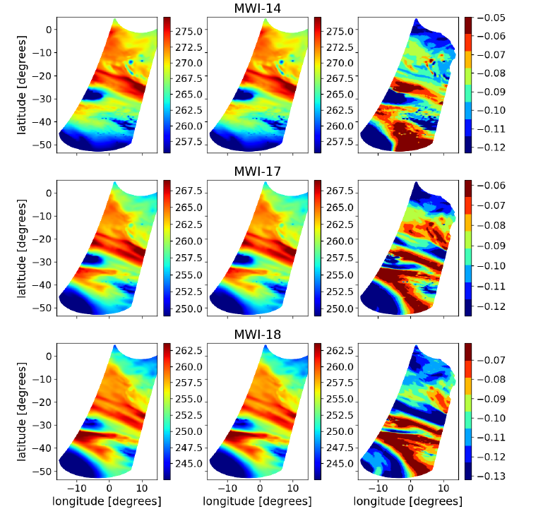
Inter-channel biases between samples from ICI-1 / MWI-14, ICI-2 / MWI-17, and ICI-3 /MWI-18 convolved to the ICI-1 FOV were assessed (Figure 2). These pairs of channels are overlapping in frequency range and are, therefore, useful to compare in a cal/val activity.